Friday, May 2, 2014

IntoElectronics Series | 01 Transistor as Switch

The first usage of transistor in electronic devices is switching. Transistor can switch the circuit on/off by given an input voltage. In this article we will show you how to use transistor capability of switching current by impalement NOT gate.

Materials:
  • 2 NPN transistors
  • 2 LEDs
  • breadboard
  • source of voltage(i.e. battery)
  • wires 


Configuration
Given:
2 LEDs: LED1 and LED2
2 Transistors: Q1 and Q2
We will make LED1 by default switched on, and LED2 switched off, when we push a button (provide current) the LED1 will become off and LED2 will be turned on. When we release the button the LED1 will be switched on and LED2 will switched off. The following video illustrates the releasing process “by cut off the current”).


To make such circuit to work we have to provide the NOT gate, when the input to this gate is on(1) its output will be off (0), when the input is off(0) it provides on(1). Transistor facilitate the switching option like that, so to start implement the NOT gate, let’s take look of how transistor configure to the circuit so it can work as switch.
Transistor has two types: NPN or PNP

To make any one of them work you have to use their legs (collector, base, emitter). Let’s focus in the NPN type (the same applied to the PNP but by converting the signs)

NPN Transistor
If you connect the transistor in the following manner:
Collector -> ground (low voltage) -> to the cathode of LED
Base -> high voltage
Emitter -> ground
The emitter-to-collector circuit will be closed and therefore the transistor will act as switched on.
When base changed to be low voltage, the emitter-to-collector circuit will be open (no current), therefore the transistor will act as switched off.
When collector is connected to high voltage instead of low and with the anode of LED.
if base is connected to low voltage, then the emitter-to-collector circuit is open and therefore the output to the LED is high because it connected to high voltage
if base is connected to high voltage, then the emitter-to-collector circuit is closed, and therefore the current will move from source voltage (provided to collector) to the emitter which makes the voltage output to the LED zero.


so the two configuration of these transistors will be used to achieve 01,10 result  for LEDs:
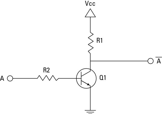

Schematic diagram:

Simply these diagrams tell you:
Q1
C -> Ground + LED cathode
B-> R1
E-> Ground
Q2
C-> 3V + LED anode
B->R1
E-> Ground
LED1
Cathode -> Q1_C
Anode -> R2 -> 3v

LED2
Cathode -> Ground
Anode -> Q2_C

C: collector, B:base , E:emitter

When you connect to B a low voltage:

When you connect to B a high voltage:

And that’s all.

Resources:
Electronics Projects: How to Create a Transistor NOT Gate Circuit: http://www.dummies.com/how-to/content/electronics-projects-how-to-create-a-transistor-no.html


Wednesday, April 23, 2014

IntoElectronics Series | 00 The Basics

During your building robot journey, you may stop many times trying to understand some parts of Arduino chip, even more you may explore some available projects of building a simple digital clock for example the following: Digital Clock without Shift Register and got stuck with many components which you don't know anything about them. You have two options, either (1)to follow the steps and apply without any question, and after things work you will try to understand; and it’s a fantastic way to get things done quickly! Or (2) you decided to just read about these things one hour or two and then make your own design! For both ways, you have to read about these unknown things, but the second approach lead you to learn before buy things and connect.

We used to follow step 1 in building our project parts, after a while, during building big parts, things became unstable, missed components and missed knowledge. Many problems have been appeared, voltage source is not enough, motors damaged, Arduino is about to say : you will burn me..stop playing! And problems became to be serious, can’t finish our project prototype! without understanding, we are wasting our time.. it’s time to understand, to gain some basic knowledge, to make things run correctly.
For that these reasons, IntoElectronics series are here, we will explore with you some quick resources that we used to understand electronics basics needed to complete our journey. Each resource is tagged with what you are going to know from it. In each article of the series we will explore many resources and trying to make some circuit run here.

Today article is about the electronics basics, take a little mins refresh your electronics background with the following resources:

Refresh #Electronics_Basics
What’s electricity? What’s electronics? What’s current? Voltage? Resistance? Ohm law’s?
Video: Introduction to Electricity  #5mins #From the beginning what’s electricity? #Flow of electrons
Video: Electricity and Circuits #8mins #Parallel/series circuits
Video: Ohm's Law #4mins #Relation between Current Voltage and Resistance
Video: Alternating Current(AC) vs. Direct Current(DC) #10mins #find difference between AC and DC
Quick Reading: How electricity works? #Simple #from how stuff works series, make you clearly absorb the big picture of things.  

More Electronics Components #explore_basic__electronics_components
If you are not familiar with things like transistor, resistors and capacitors then it’s a good start to take a look for each component, understand the behavior of each and then we can build circuits! It’s not necessary to try it by your hand now, try to grasp the idea behind each component and there will be a detailed explanation and practice for each component in a separated post. 

Breadboard
Video: Electronics - Breadboard #8mins #Breadboard for building/testing circuit

Resistors
Video: Electronics - Resistors #7mins #Resistor Color Code & its effect on the circuit.

Capacitors
Video: Introduction to Capacitors #9mins #understand what the capacitor is

Transistor & Diode
Quick Reading: How Semiconductors Work #Simple #from how stuff works series, make you clearly absorb the big picture of things.  #semiconductor as basic part of knowing what does diode and transistor mean?
Video: MAKE presents: The Diode #8mins #Diode #from where did Diode come?
Video: PN-Junction & Diode #5mins #demonstration of np junction that form a diode
Video: How Does a Transistor Work? #6mins #demonstration of semiconductors and transistor behavior
Video: Electronics - Using an NPN Transistor as a Switch #7mins #quick application of transistor

Integrated Circuit
Video: MAKE presents: The Integrated Circuit #6mins #what IC is  #quick review of its history

Sunday, February 23, 2014

Project3 | Light Detector


Your children or your brothers or sisters having fear of darkness! Make a night light that automatically goes on when you turn off the lights. by using a light sensor, some wires, and LEDs you can easily create an automatic night light that will turn on when you turn off the lights.


Configuration


By following the diagram, you can notice the following:

The photocell (light sensor) is connected via there wires:
(1)Blue and black wires to one of photocell legs and (2) red wire to the other leg. A resistance is added along the photocell connected to ground (black wire). These wires are for:
·         Black wire à ground
·         Red wire à 5V
·         Blue wire à analog input A0 ( because photocell give analog data)

Code


1.       Some required definitions, which PIN the LEDs and photocell is connected to?
int LDR = 0;   //analog pin = A0
int LED1=3;
int LED2=4;
a.       Define light sensitivity, the threshold we want to control lights according to it, if the photocell senses a light less than this threshold, then turn LEDs on
int light_sensitivity1 = 300;
int light_sensitivity2 = 50;
b.      Define a variable to store the value which photocell senses
int LDRValue = 0;

2.       Set the LEDs pins to output mode, open the serial (optional) for output on screen
Serial.begin(9600);               
pinMode(LED1, OUTPUT);
pinMode(LED2, OUTPUT);

3.       Start listen to the photocell, put what the sensor reads to LDRValue
LDRValue = analogRead(LDR);              Serial.println(LDRValue);  // cout << LDRValue;
delay(50);                                               

4.       We will turn on the first LED, if the value read by the sensor less than the first light sensitivity (i.e. 300), the second will turn on, only when the LDRValue is less than the second light sensitivity ( more darkness)
if (LDRValue < light_sensitivity1){
     digitalWrite(LED1, HIGH);
     
     if (LDRValue < light_sensitivity2) 
           digitalWrite(LED2, HIGH);
     else
           digitalWrite(LED2, LOW);
}else{
        digitalWrite(LED1, LOW);
      }

Saturday, February 8, 2014

Project1-Phase2 | "Say what Requested! "


In the previous phase of the project, we automatically display the number on the 7-segement display in ascending manner. Now we want to add another feature, using Serial Port/USB, we want to send the number to display from computer to Arduino(i.e. the 7-segement will display the number I choose, when I send 1 from computer, I want the 7-segment to draw the 1 number, send 2 then display number 2 and so on) how to do that?


Send Data using Serial Port/USB connection
Using the USB connection between Arduino and the computer, we can send data from computer to Arduino. How to do that? We will modify in the previous code in the following meaner:  We will add 4 functions:

(1)Serial.begin(9600);
Serial is a part of existence library in Arduino. Using serial means you want a connection between the PC and Arduino. To ask Arduino to start a connection between him and the PC we call this function begin() .. begin() take a great number, the question will rise immediately what is this number? This number is the speed of connection, 9600 bits per second .. each second serial can send 9600 bits... it’s like your network download speed.

(2)  Serial.println(“Enter the number you want to display please”);
This is a message which Arduino will send to the computer request the user to enter a number..Well we need a receiver!

(3)Serial.read();
This is what receives bytes from user, on Arduino, to read over the serial connection, we use this function as our cin operator.
As cin need a variable to receive the input in ( cin >> x ) then her two we need a variable to hold the  user input.. well give me a variable.. But what does the function return? What’s the type? It returns the first byte received as integer.
int byteReceived= Serial.read();
With this byte, I can do many things, I can print it (send it back to computer), I can do condition on it to light up the LED and we can us it in our project to print the specific number to the 7 segment. But I can to receive it in char/byte format, as the returned type can be casting to these types.

(4)  Serial.available() this function this is there any one send data over the serial port? If you send a data this function return true, you then can take what sent by calling Serial.read()
The complete code:
Using the function of pervious project, we will add on the setup the Serial.begin(9600) in the loop we will make some if conditions that restrict the output to the display on the 7-segement.
if (Serial.available()){
char byteReceived= Serial.read();
if (byteReceived == ‘0’ ) // if you receive a character 0
lightUpSegement(0); // display zero on the 7-segement
if (byteReceived == ‘1’ ) // if you receive a character 1
lightUpSegement(1); // display one on the 7-segement
if (byteReceived == ‘2’ ) // if you receive a character 2
lightUpSegement(2);   // display on the 7-segement
...
}

Or simply by using for-loop:
if (Serial.available()){
for(int i=0; i<9 ; i++)
if (byteReceived == (char)(i+‘0’) ){ // if you recive the ith character
lightUpSegement(i);   // display this ith number
break; //enough execution :)
}
}

How to open connection with Arduino and send data?

(1) Form the Arduino IDE, Serial Monitor

(2)You will find Arduino asks you to enter a number:

(3)Enter the number in the text box and click send
(4) Check Your Robot:

Saturday, February 1, 2014

Project1-Phase1 | "Robo,Say the Numbers!"

Phase1: Basic Counter

When you need to teach your child the numbers you start to teach them numbers in ascending order. “Hey .. first number is 1.. 1 means one thing.. When I have 1 and another 1 that means we have two things.. Then 2 is a number means 1+1 .. etc” You then will ask him/her to counting up the numbers: “Tell me the numbers from 0 to 9”.. and the child start to be like a counter ( 0,1,2,3,4,5,6,7,8,9). Our first robot in this series, is this child.. We make a child with 7 figures (as bulb) to say the numbers..


The 7-segments Display
Robot’s fingers, they aren't like ours it’s more simple.. It’s a collection of LEDs which make the basic element in most of display monitors in our digital life.
We see the 7 segment every day! We see and use it everywhere in our digital life and get benefits from it, without the 7 segment we think the life will be a little bit horrible!

The 7-segments this is our story hero, the figures, the basic element of display monitors in calculators digital alarm clock, gas station & price changer signs, stock market, on microwave oven display screens, عداد اجرة التاكسي... etc.
This element to be used correctly we have to understand its physical construction, we have to understand how we can give a power to it, and how to control the lighting of each segment?

Anatomy of 7-Segment Display
When you are going to explore the component, you will figure that there are 10 pins in the 7 segment; each PIN wired one segment! 10 PINs and you said 7 Segments? There is a decimal point, the small dot on the bottom right, and then now we have another pin for dot, 8 PINs know now. There are still two PINs? For what these PINs for, you will know soon.
First, we need to identify PIN1 in order to probably assign a power (+) and ground (-) to the pins. This information is found on the technical specifications sheet also known as the "data sheet”. Second, every PIN lights up a segment; we can give each segment a letter:
PIN1 -> E  , PIN2 -> D , PIN4 -> C , PIN5 -> DP "Decimal Point" , PIN6 -> B, PIN7 -> A
PIN1
E
PIN2
D
PIN4
C
PIN5
DP
PIN6
B
PIN7
A
For PIN3, PIN8, they will be connected to the ground if you work with "7 segment Common Anode" but if you work with "7 segment Common Cathode “then you have to connect the these PINs to the power(5V).. What’s the common cathode and anode stands for? Follow this tutorial for more information


Now, we know the parts of the 7 segment and we are ready to learn how to use it and light them up!

Build the Robot
Hardware Components:
·         Arduino chip ( we use Arduino Uno)
·         Breadboard
·         1x 7segement display
Steps to make robot ready:
(1) Put the 7segment in the bread board 
(2)Start to connect Arduino Digital PINs with 7-segement PINs, in the following manner:
PIN  in the 7segmant
Digital Pin in the ARDUINO
1
2
2
3
3
5V *
4
4
5
-
6
5
7
6
8
5V *
9
7
10
8

* Because we use common cathode 7-segment display
(3) Connect the ARDUINO  to PC to start uploading the sketch to Arduino

Teach the Robot

We are ready now to teach the robot(write and upload the sketch to the Arduino). Well, first we want to identify our problem:
We want to display the numbers starting from 0 to 9 in the 7-segement display.
To start search of where we can start write the code, we want fist to identify the PINs we will turn it on and off (the PINs of Arduino). By the way we used in connecting the Arduino to 7-segement, we can say:
int segementPINS[]={2,3,4,6,7,8,9}; // 1 2 4 6 7 9 10
                                    // E D C B A F G
This array say that the PIN number 2 in Arduino, connected to the E segment, so when we send a high signal to this pin, E segment will turn one(note: that we are using common cathode, that the segment won’t turn on except we send a low signal..make sure for your 7-segment component). The same is  for the other elements of the array.
To display the number on 7 segments, we have to say for each number which segment will turn on/off. For instance to display the number 0, all segments should be turned on except segment G. so we can draw a truth table for 7-segments with numbers

E
D
C
B
A
F
G
0
1
1
1
1
1
1
0
1
0
0
1
1
0
0
0
2
1
1
0
1
1
0
1
3
0
1
1
1
1
0
1
4
0
0
1
1
0
1
1
5
0
1
1
0
1
1
1
6
1
1
1
0
1
1
1
7
0
0
1
1
1
0
0
8
1
1
1
1
1
1
1
9
0
1
1
1
1
1
1
We store this table in 2D array:
int nums[10][7]={{1,1,1,1,1,1,0}, /* 0 */
                 {0,0,1,1,0,0,0}, /* 1 */
                 {1,1,0,1,1,0,1}, /* 2 */
                 {0,1,1,1,1,0,1}, /* 3 */
                 {0,0,1,1,0,1,1}, /* 4 */
                 {0,1,1,0,1,1,1}, /* 5 */
                 {1,1,1,0,1,1,1}, /* 6 */
                 {0,0,1,1,1,0,0}, /* 7 */
                 {1,1,1,1,1,1,1}, /* 8 */
                 {0,1,1,1,1,1,1}  /* 9 */
                 };
To turn the segment on we simply make a function “void lightUpSegement(int num)” that take the desired number to display num. this num is the first index of nums array(i.e. the row number). If we want to display number 3 ( num=3) then we want row=3 ({0,1,1,1,1,0,1}) we have this row, access each element by a for loop if the element equals 1 then we have to turn the segment on:
digitalWrite(segementPINS[j],LOW); // turn on : common cathode
Else (equals  to 0)
digitalWrite(segementPINS[j],HIGH); // turn off : common cathode
In the loop function, make a for loop that calls lightUpSegement function for each number between 0 and 9, and of course set some delay between each display
for(int j = 0 ;j <10 ; j++ )
   {
    lightUpSegement(j);
    delay(2000);
   }
Don’t forget to state in the setup function that segementPINS is used as output PINs
void setup(){
  for(int i = 0 ; i<7 ; i++){
  pinMode(segementPINS[i], OUTPUT);
  }
 }

And we are done! Verify, upload.. and your robot start to counting the numbers : )